Understanding the RAN wordsoup

C-RAN, D–RAN, vRAN, O-RAN - Is C-RAN the same as Cloud RAN? The RAN wordsoup is exhaustive and sometimes - ok, most of the time - very confusing. And that's not taking into account various other accompanying acronyms such as HLS, LLS, DU, CU, CPRI, eCPRI, or RoE, etc. The previous blog described the evolution of RAN in mobile networks, culminating in what is today called Cloud RAN. This blog will explain some essential RAN terminologies and acronyms to provide a clean and concise description to the readers.
3GPP
The very first acronym everyone should be aware of is 3GPP. The 3rd Generation Partnership Project (3GPP) started as a consortium of mobile networking vendors, working together to define specifications for mobile networking. This consortium released its first set of specifications called Release-99 (ironically released in the year 2000) as part of 3G specifications. Though the group was initially formed with 3G in mind (hence the name) it has continued to exist and define specifications for further development and enhancements in mobile communication.
Subsequent releases of 3GPP specifications were numbered sequentially (starting at Release 4), with Release 18 currently in progress, as of Oct 2022. It is important to understand that while each release of 3GPP defines specifications and enhancements, the releases are not associated with a specific generation of mobile communication. Also note that each mobile generation implements features and specification across multiple releases as technology matures and features evolve. Hence, the terms 3G, 4G, 5G etc. are therefore not directly mapped to, but associated with, one or more 3GPP releases.
RAN Disaggregation vs RAN Decomposition
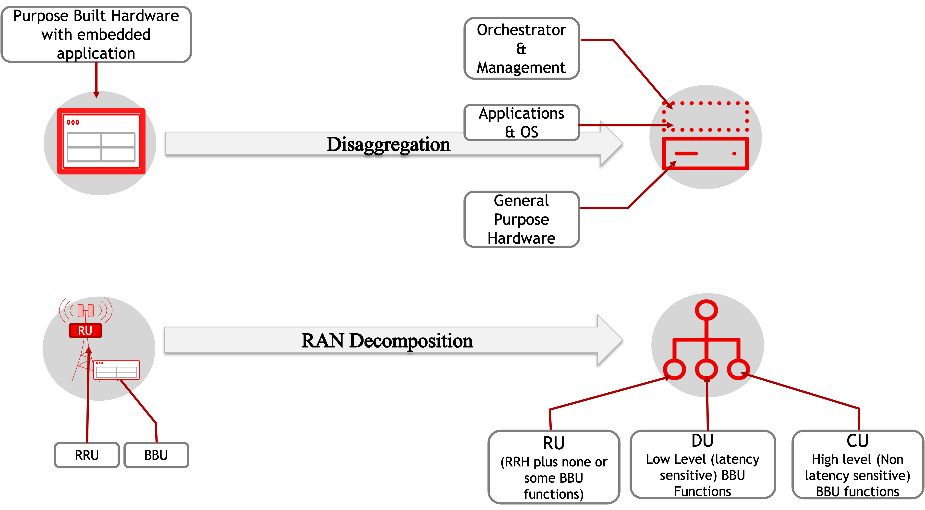
Disaggregation and Decomposition of RAN may sound similar, but they imply two distinct aspects of the next generation Cloud RAN architecture. Disaggregation of RAN refers to the virtualization of RAN software to enable RAN functions to be hosted on general purpose COTS hardware. In contrast, the decomposition of RAN is used to describe the breaking down of RAN’s functions into newly defined components of RU, DU, and CU as defined by the RAN Functional Split Options. The figure below captures the contrast between these two concepts:
RAN Functional Split Options
With RAN decomposition, the functionality of the BBU has been distributed into three separate components, the Radio Unit (RU), Distributed Unit (DU), and Centralized Unit (CU). 3GPP has defined multiple possible options to determine the BBU functions that would go into the RU, DU, and CU.
These RAN Functional Splits, simply called split options, range from Split Option1 through Split Option 8. Effectively, these split options refer to where the functions defined by the 5G Protocol Stack layers (i.e. PHY, MAC, RLC, PDCP, and RRC layer) will be split between the RU, DU and CU. The figure below shows the split options defined by 3GPP.

It must be noted that other standard bodies (such as Small Cell Forum, eCPRI forum) have also defined their own Split Options, which in most cases, aligns with 3GPP defined split options. 5G functional split overview by Huber+Suhner is a very good and concise reference to understand and compare Split Options defined by 3GPP, Small Cell Forum, eCPRI and others.
These Split Options can be further classified into Higher layer Split (HLS) and Lower Layer Split (LLS) options.
HLS and LLS
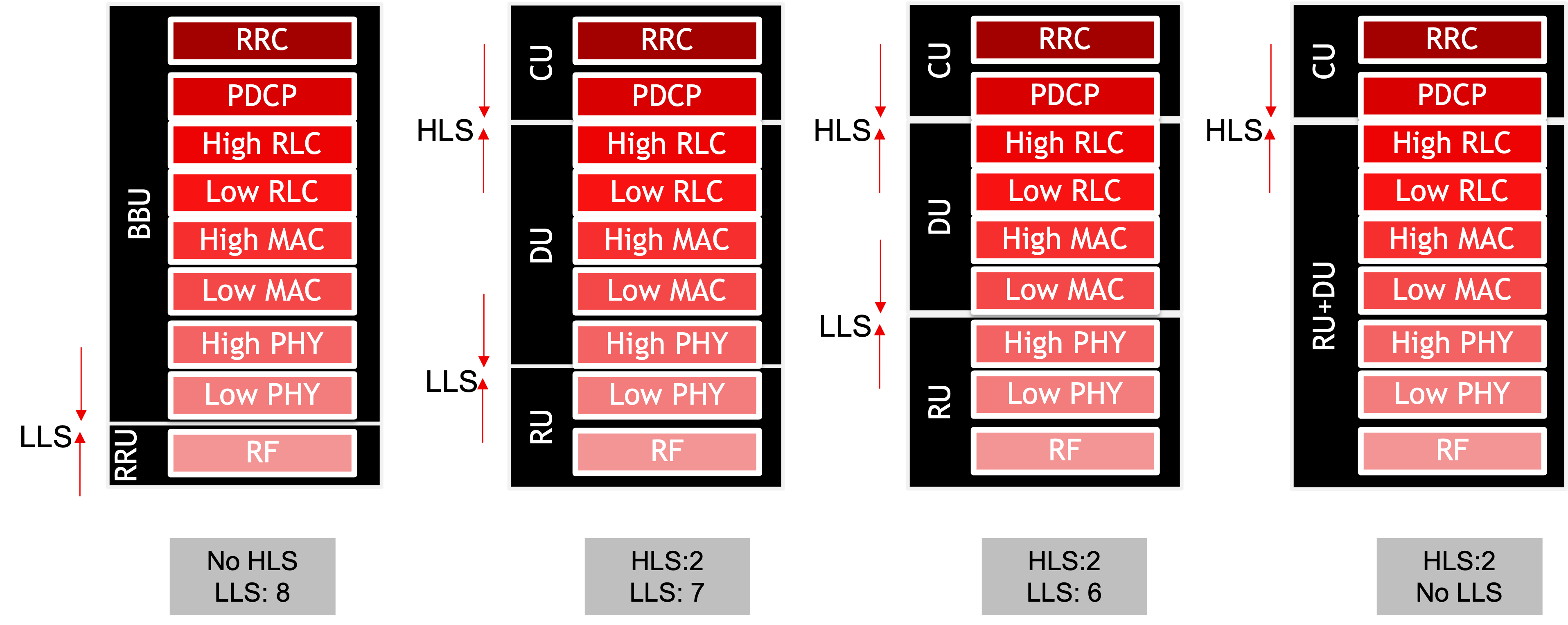
The split options determine the distribution of the 5G protocol stack (originally implemented by the BBU) between the RU, DU and CU. The split that determines the functions between the DU and CU is called Higher Layer Split (HLS), while the Lower Layer Split (LLS) defines the RU and DU responsibilities. A RAN implementation may be done with one or both of these splits.
The following figure shows some examples of split options. Note that using LLS Option 8 without using HLS is analogous to using traditional RRU and BBU similar to 4G.
DU and CU
The terms Distributed Unit (DU) and Centralized Unit (CU) are used to describe subset of functionalities that were previously performed by BBU. Despite the names, in real world deployments, the CU are typically but not necessarily placed centrally, and the DU implementation doesn't have to be geographically distributed. More details on this are covered in the Centralized RAN and Distributed RAN definitions.
The exact distribution of functions between the DU and CU is dependent on the split option being used - more specifically the HLS. Multiple possible options have been defined by 3GPP with a recommendation for Option 2, and as such it has therefore been adopted as the industry standard. An LLS option recommendation was not agreed upon by 3GPP, and left to the discretion of industry players. The O-RAN alliance, discussed later in the blog, has defined Split Option 7-2x for LLS, which has become the industry favorite for RU-DU functional split for traditional cell sites.
Centralized and Distributed RAN (C-RAN & D-RAN)
In the majority of current RAN deployments, primarily 4G, the RAN components (Antenna, RRU and BBU) are placed in close proximity to each other at the cell site. Each of these sites were self-contained as a RAN entity (called evolved NodeB, or eNB in 4G jargon), and didn’t rely on any central RAN component (such as RNC in 3G). This was the only deployment model in initial 4G implementations.
However, in the later part of 4G and now in 5G the concept of pooling the BBU devices at a central location was introduced. To represent this deployment model of BBUs pooled at a central location serving multiple cell sites, the term Centralized RAN or C-RAN was coined. The earliest use of this term was in 2010 by China Mobile Research Institute along with some mobile hardware vendors such as Nokia and ZTE. To contrast with C-RAN, the RAN deployment model with the BBU residing at the cell site was labeled as Distributed RAN or simply D-RAN. Note that in the C-RAN model, there will still be multiple (geographically dispersed) locations for hosting the pooled BBU functions. The C-RAN model also gives birth to the Fronthaul network - i.e. the network that provides RU-BBU connectivity.
The splitting of BBU functions into DU and CU gives a new perspective to the C-RAN definition. In a decomposed RAN, the location of the DU determines whether the deployment can be classified as C-RAN or a D-RAN. When the DU is collocated with the RU, it would be considered D-RAN, and if the DU is deployed away from the cell site then it's a Centralized RAN deployment model. To summarize:
- Both CU and DU on the cell site. This will essentially make it a D-RAN deployment, similar to when BBU is placed at the cell site in 4G LTE scenarios
- The CU is at a remote datacenter location, but the DU is at the cell site. This too will be considered a D-RAN deployment due to DU being collocated with the RU
- The DU and CU are collocated but implemented in a Data Center away from the cell site. That will be considered a C-RAN deployment due to DU being away from RU.
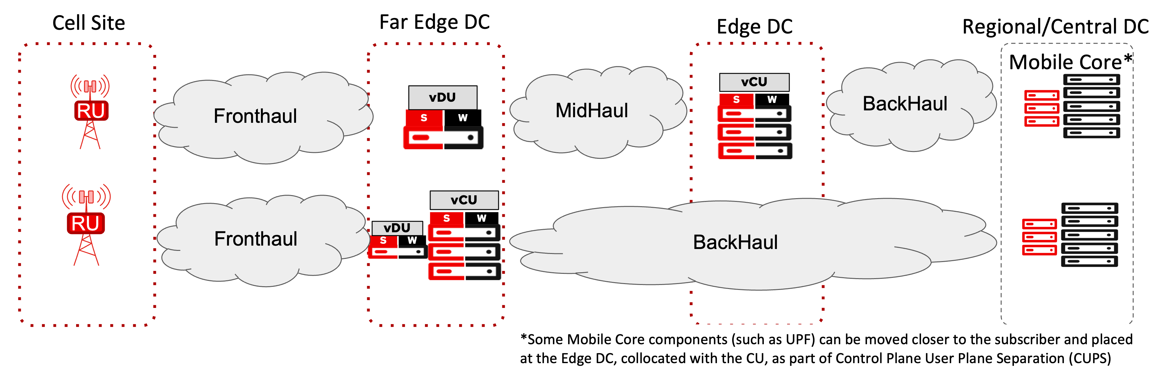
- The DU and CU are implemented away from the cell site in separate datacenter locations. This will also be considered C-RAN with two C-RAN Hubs - one to host the DUs (also called Far Edge Data Center), the other to host the CUs (also referred to as Edge Data Center).
The visualization of a Centralized RAN, design where DU is away from RU, either with or without a collocated CU, is shown below.
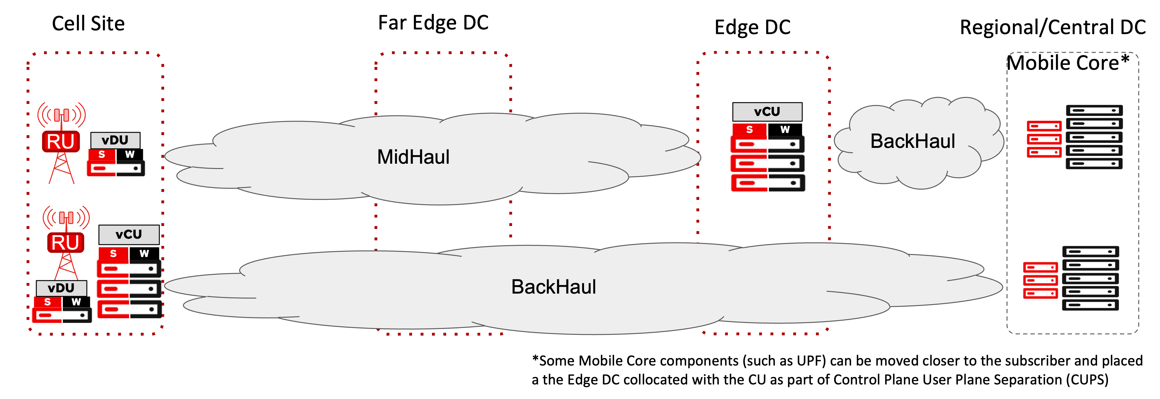
Similarly, a distributed RAN design, i.e. where a DU is collocated with RU, either with or the without CU, is shown below
Open RAN, O-RAN and OpenRAN
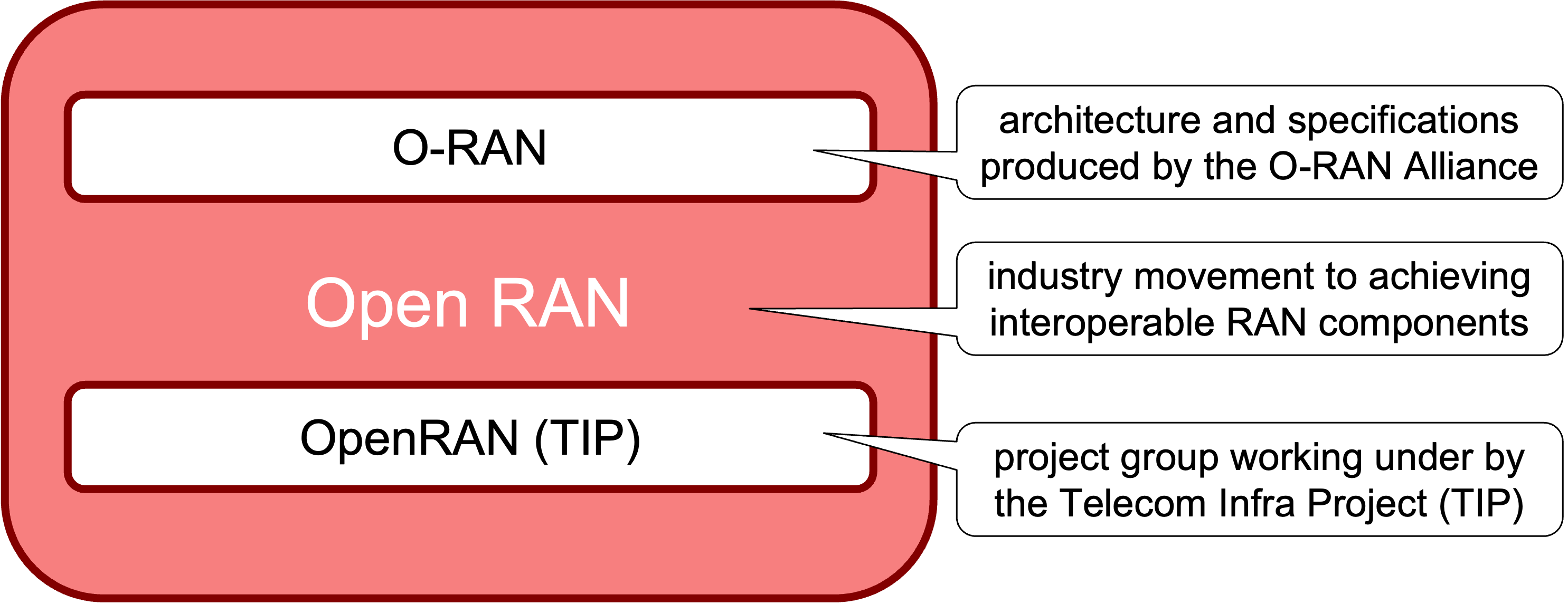
Though O-RAN and Open RAN and OpenRAN (i.e. without the space) are often used in the same context, they are not one and the same.
Open RAN is the big picture industry movement that encompasses any RAN solution focused on achieving interoperable RAN components through Open interfaces between RU, DU and CU. This allows operators to break free of vendor lock-in, and implement these functions using a diversified set of vendors.
To influence the industry towards Open RAN, a consortium of mobile operators formed and led an industry alliance named O-RAN aimed at defining an architecture that supports open interfaces between the RAN components. Many networking, mobility, and test equipment vendors as well as academic institutions have also subsequently joined the alliance and now collaborate with the operators to collectively achieve a fully open RAN. Today, the term O-RAN refers to the architecture and specifications produced by the O-RAN Alliance.
Another effort towards Open RAN is defined by the Telecom Infra Project (TIP). TIP is a group that includes operators and equipment manufacturers that has the sole goal of providing connectivity solutions. When it comes to mobile communication, an open RAN paves the path towards cheaper and more versatile RAN and hence TIP started a project group called (confusingly!) “OpenRAN” (i.e. Open RAN but without the space). OpenRAN is not an alternate approach to O-RAN, rather it takes specifications from O-RAN, and implementation of RAN functions based on CNCF (Cloud Native Container Foundation, yet another organization advocating for openness of software) and then evaluates their integration, interoperability, and functional validation.
The following figure provides a visualization of the relationship between O-RAN, OpenRAN and Open RAN.
vRAN
One of the initial use cases that were envisioned by the Network Functions Virtualization drive was the virtualization of RAN; more specifically BBU at that time. Virtual BBU, or vBBU never really took off, but with more mature technologies in the 5G era, its decomposed components, i.e. DU and CU are now virtualized. A RAN deployment that uses virtualized CU (called vCU) and/or virtualized DU (vDU) is referenced as a vRAN deployment.
Note that the term “virtualization” is being used in a generalized manner, referring to both virtualization through virtual machines, or virtualization using containers (sometimes called “containerization” to differentiate).
Virtualization of RAN is an orthogonal concept compared to Centralization of RAN. A vRAN implementation can simultaneously be Centralized RAN (C-RAN) as well i.e. the vDU is implemented away from the RU, with CU either at the same location as DU or in a different location. Similarly, a vRAN implementation can be Distributed RAN (D-RAN) with the vDU (and possibly even the vCU) implemented at the cell site, collocated with the RU. Both these concepts are discussed and visualized previously in this blog.
Cloud RAN
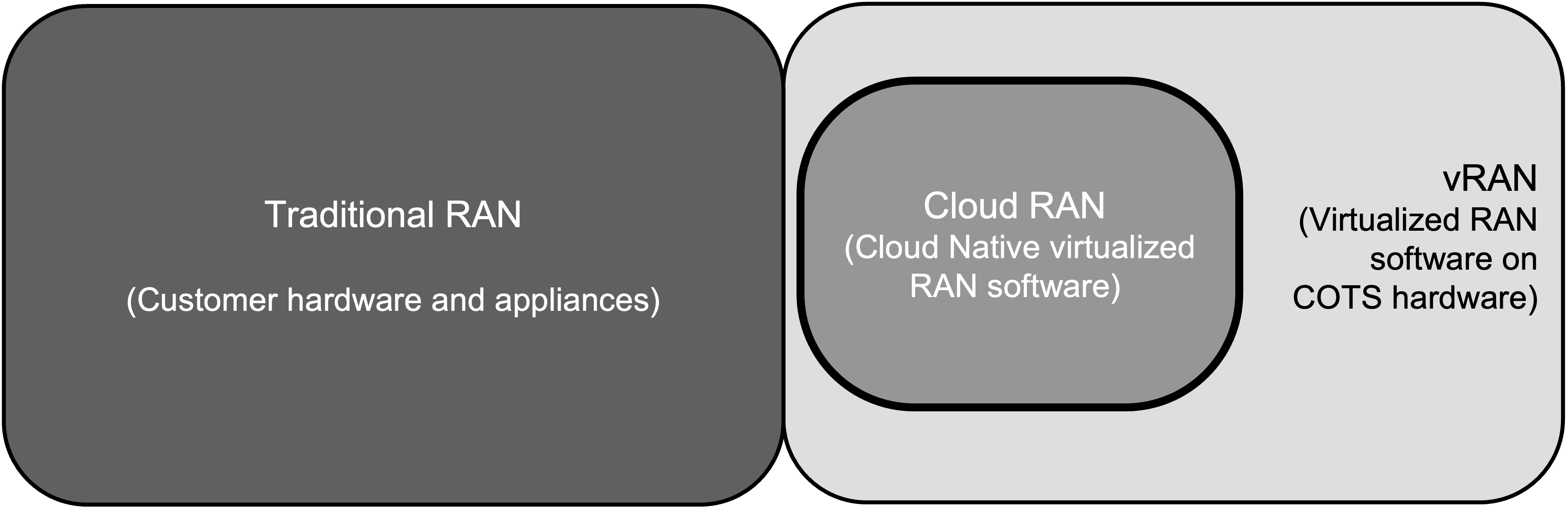
Cloud RAN is an evolution of the vRAN architecture. Though often equated with vRAN, strictly speaking Cloud RAN implies the use of vDU and vCU that are designed to be cloud native. Being cloud native, these vDU and vCU applications are generally implemented using lightweight containers, are well suited for both public and private clouds, and devops friendly through automation and orchestration.
Note that Cloud RAN can also be abbreviated as C-RAN, which may be confused with Centralized RAN. However, as explained earlier, the virtualization of RAN, and centralization of its components are two orthogonal and independent concepts. The following figure shows the relationship and overlap (where applicable) between Cloud RAN, vRAN and traditional RAN.
CPRI
Common Public Radio Interface (CPRI) is the specification that defines the communication between the RRU and BBU. This specification was needed when RRU was detached from the rest of radio processing equipment (now called the BBU) and moved to the top of the cell tower, alongside the antennas - a process that was explained in the previous blog. Even though major radio equipment vendors got together and agreed on the basic CPRI specifications, the actual implementation of CPRI may be proprietary. Hence the RRU from one vendor can’t be expected to work seamlessly with BBU of another vendor due to possible incompatibility between the CRPI implementations the two vendors may be using.
CPRI was defined to use constant bit rate traffic (i.e. fixed amount of traffic irrespective of the actual traffic load of the radio service), and hence consumes a high amount of bandwidth. Different rate options have been defined for CPRI, and depending on the radio signal’s bandwidth, the appropriate rate option may be used for CPRI traffic from/to an RU. The CPRI rate options are specified using numbers, and range from 614.4 Mbps (Rate option 1) to 24.33 Gbps (Rate option 10). Though not a requirement, given its high (and constant) bandwidth consumption and sensitivity to signal degradation, CPRI is always carried over fiber links.
Radio over Ethernet (RoE)
Radio over Ethernet (RoE) is an attempt by IEEE to allow CPRI transport over an Ethernet/IP network, defined by IEEE specification 1914.3. Using Ethernet/IP transport opens the doors for packetized FrontHaul networks that could provide the same benefits and feature-richness of traditional backhaul networks. While RoE was a step towards IP based Fronthaul, it still required a massive amount of bandwidth due to the underlying CBR nature of the CPRI traffic encapsulated within Ethernet headers.
eCPRI
eCPRI is the evolution of the CPRI specifications that enables the communication between the RU and BBU/DU using Ethernet or IP encapsulation. As a result, unlike CPRI, eCPRi traffic can be sent over the ubiquitous Ethernet interfaces. As mentioned above, CPRI used serialized Constant Bit Rate (CBR) traffic that required an always-on, high-bandwidth connection between RU and BBU/DU. However, eCPRI shifts away from the CBR communication and sends traffic between RU and BBU/DU only when there is user data to send. eCPRI specification also pushes some of the radio data processing to the RU by using sub options within LLS option 7. Combined, these enhancements reduce the bandwidth required between RU and BBU/DU and allow for statistical multiplexing across users. Another benefit of eCPRI was the native Ethernet transport without the explicit use of encapsulation technology such as Radio over Ethernet (RoE).
Here’s a fun fact – no one knows what e in eCPRI stands for as it was never spelled out in the eCPRI specifications. But seeing as eCPRI was meant to be an evolution or enhancement to the original CPRI specification, the term eCPRI refers to evolved CPRI or enhanced CPRI. Both are commonly used and generally accepted industry terminologies. What is NOT true however, is to equate eCPRI with ethernet CPRI !!
It must be noted that similar to CPRI, the eCPRI specifications were agreed upon, but early vendor implementations added proprietary features and optimizations coming back to the same issue of vendor interoperability between RU and BBU/DU. Industry efforts such as the Open RAN movement tackled this issue, as would be discussed in the next blog.
eNodeB (eNB) & gNodeB (gNB)
The term NodeB was introduced in 3G to collectively refer to the RAN components that are co-located at the cell site; more specifically the antenna and the radio processing equipment. With 4G, the word “evolved” was added to it, making it eNodeB (eNB) to represent a 4G-based cell site. In common terms, eNB can be considered to encompass all the components that reside at the cell site - the Antenna, Radio Unit (RU), and Base Band Unit (BBU).
Another fun fact: It is more technically correct to associate the term eNodeB with Long Term Evolution (LTE), which is the accurate terminology to represent RAN evolution that accompanied 4G. But most people don’t differentiate between 4G and LTE terminologies, and hence it's acceptable to call eNB a part of 4G.
With 5G, the same RAN functions may or may not be implemented on the cell site (D-RAN vs C-RAN). Irrespective of where they are located, the collection of these functions is called gNB in 5G. The “g” here is a representation of “Next Generation” , just like the “e” in eNB represents “Evolved”. A 5G gNB comprises Antenna, Radio Unit (RU), Distributed Unit (DU) and Centralized Unit (CU)
