The Road to Cloud RAN
We often come across the question: What does Red Hat have to do with Cloud RAN? To understand the answer, one must take a step back and understand what Cloud RAN is. With the plethora of terminologies that the networking and telecom industry uses (perhaps more than any other technology domain), the terms Cloud RAN, vRAN, and Open RAN are often used interchangeably (and sometimes incorrectly) in the context of 5G. Though all of these have evolved from the previous generations of RAN, they represent different, yet intertwined, attributes of a modern RAN implementation.
Cloud RAN is an important enabler to materialize the goals set by 5th Generation of Mobile technology (aka: 5G), and Red Hat actually has a very significant and dominant role to play to implement Cloud RAN.
This series of blogs answers all the questions, curiosities and confusions that one may have about what Cloud RAN is, how mobile networks have evolved to this, its key terminologies and jargons, and most importantly, the key role that Red Hat has taken on to make Cloud RAN a reality. The first blog of the series will explain the road to Cloud RAN, and its relationship with other RAN terminologies that are often used today.
Early Radio Access Networks:
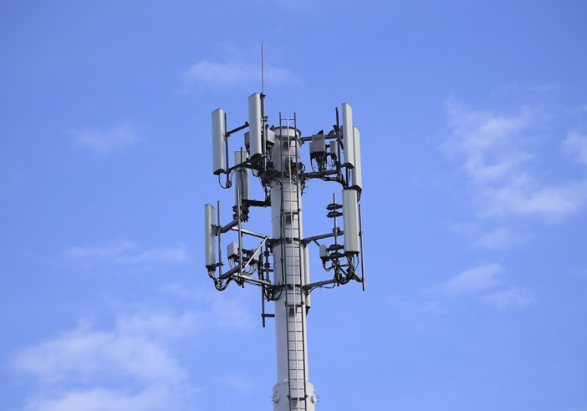
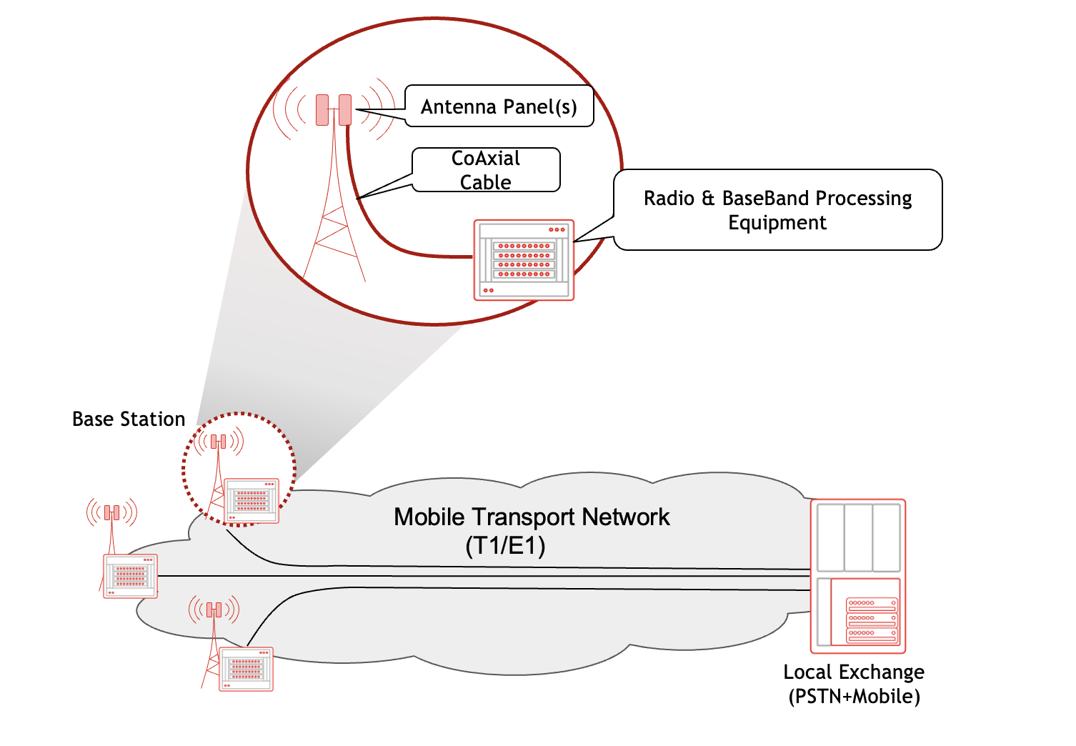
The Radio Access Network (RAN) has been an integral part of mobile networks from the very beginning. Even though the first generation of mobile networks (1G) did not define it as an independent entity, the combination of Base Station (BS) and antennas mounted on the cell tower constituted the RAN in that generation. A typical 1st Generation cellular network is shown in the following figure:
2G RAN : The Base Station Subsystem
It was in 2G where the Base Station Subsystem (BSS), comprising the Base Transceiver Station (BTS) and the Base Station Controller (BSC), was introduced which evolved into today's RAN.
With 2G, the following three domains could be easily distinguished in a mobile network:
- The mobile call processing and switching functions deployed at the central sites, which 2G called a Mobile Core.
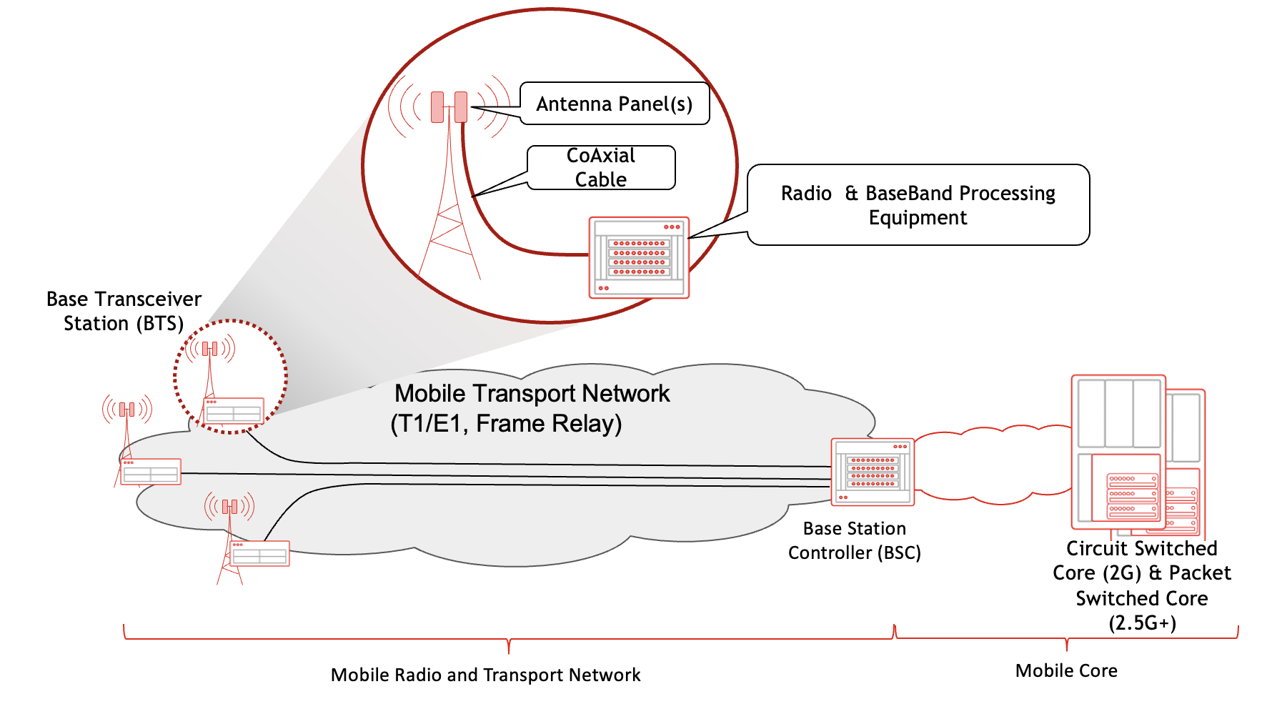
- The radio components dubbed the Base Station SubSystem (BSS), that comprised a mesh of Base Transceiver Stations (i.e. cell towers) and a Base Station Controller (BSC) for a group of Cell towers:
- There were two very visible components at each tower:
- the antennas mounted on top of the tower, and
- the radio signal processing equipment that was placed in a temperature controlled enclosure at the base of the tower.
- BSC introduced a modular, extensible and scalable RAN architecture to address scalability and grown concerns
As shown in the following figure, the two main pieces of equipment at the 2G Cell Tower - the antennas and the radio processing gear - were still connected using a Coaxial cable that carried the signal from the passive antennas at the top of the tower to the equipment at its base. However, this use of coaxial cable caused attenuation and signal degradation, resulting in suboptimal RAN coverage and performance - an issue that was addressed in 3G with the introduction of Radio RadioHead (RRH)
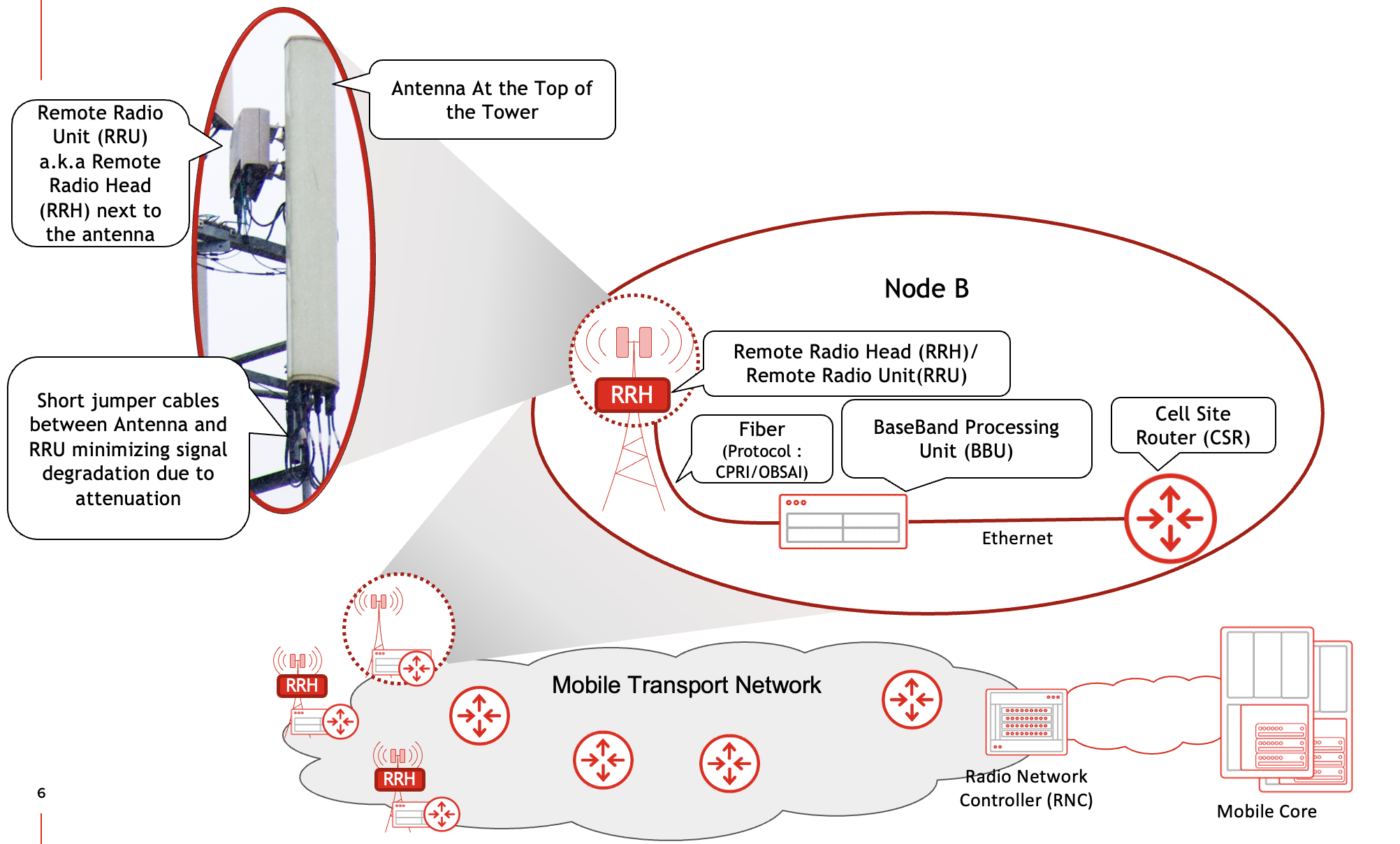
3G RAN: NodeB & RNC
3G formally laid the foundation of the RAN by introducing the term NodeB. 3G's NodeB separated the Radio Unit, that was previously implemented with the rest of the radio processing equipment, and moved it as a standalone device to the top of the tower closer to the Antennas thus making it remote to the remaining radio equipment at the base of the tower.
This device, aptly referred to as Remote Radio Unit (RRU) or Remote Radio Head (RRH) was connected to the antenna using short jumper cable, which solved the challenge of signal degradation due to the use of long coaxial cable that needed to run the length of the tower.
The remaining functions of the BTS were now performed by the device referred to as Base Band Unit (BBU) - still residing at the base of the cell tower. As the names imply, the RRU would process the modulated radio signals from the antenna, and then pass the baseband (unmodulated) traffic to the BBU, which would then perform the processing of both control and data traffic.
An optical interface was used for communication between RRU and BBU running a protocol called Common Public Radio Interface - abbreviated as CPRI. Another important change was the shift towards ethernet based data networks to carry traffic from the cell sites. In early 3G networks, a Layer 2 switch was typically co-located with the BBU at the cell site and provided Layer 2 connectivity between the BBU and the rest of the mobile network. As technology evolved, low end routers would replace this switch at cell site, thus giving birth to the term Cell Site Router (CSR). These CSRs would eventually use MPLS VPN (i.e L3VPN) for backhauling the mobile traffic from cell sites to the mobile core. The functions of the BSC in 2G (Call-Handoff, Coordination between cell sites, etc) were performed by what is termed as the Radio Network Controller (RNC) in 3G. Each RNC managed multiple NodeBs in its region.
The following figure outlines the RAN components and their placement in 3rd Generation Mobile networks.
4G RAN: Introduction to Distributed-RAN & Centralized-RAN
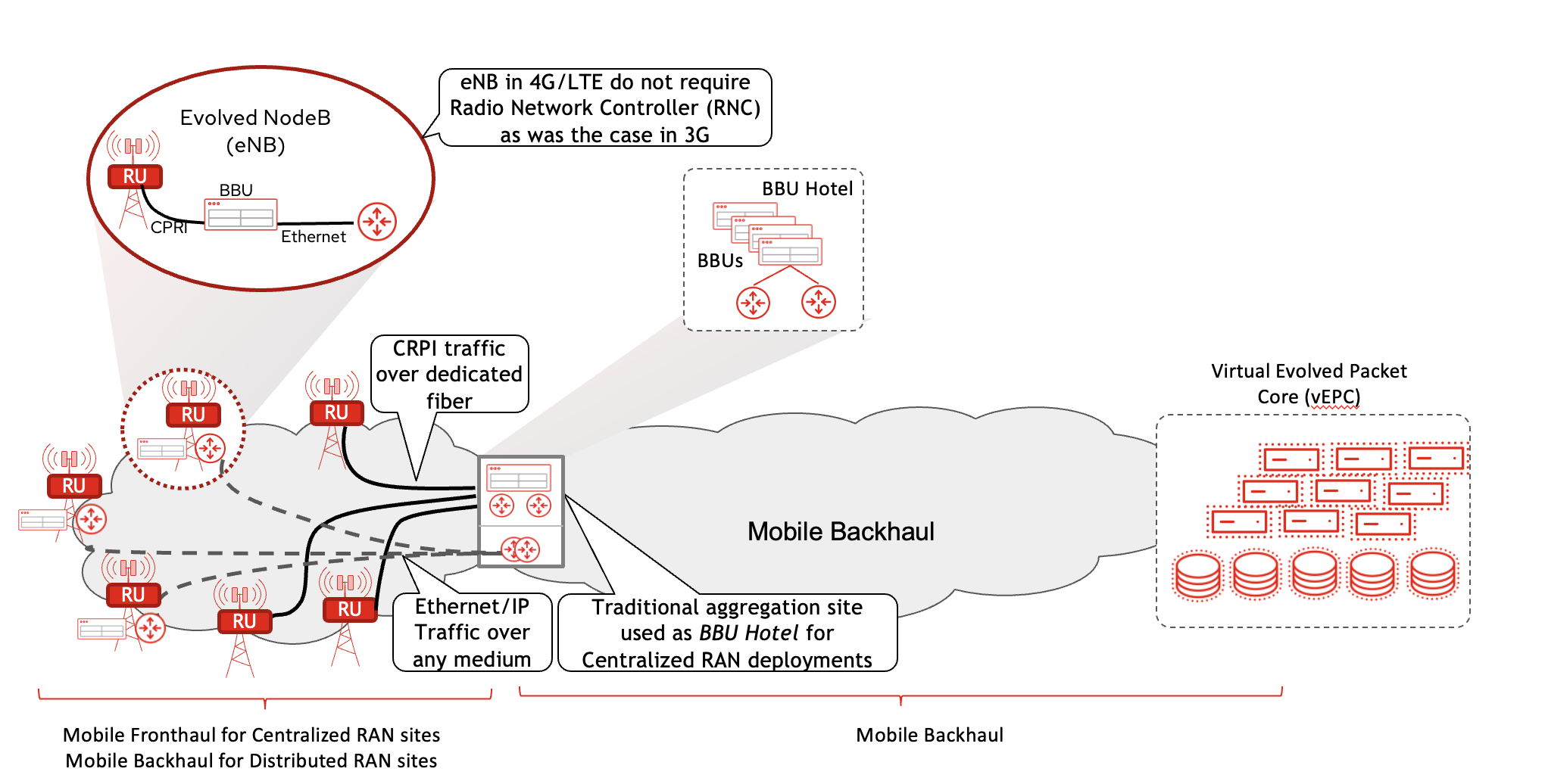
These transitions paved the path for 4G, which brought major innovations in the Mobile Core (now called Evolved Packet Core, or EPC), and radio technology (referred to as Long Term Evolution, or simply LTE). One of the fundamentation changes from the perspective of RAN was the elimination of RNC as a separate entity with its role being absorbed into the BBU. Now, every cell site was a self contained RAN entity comprising the Antenna, the RU and the BBU - referred to as an evolved NodeB or eNB.
It was in the later stage of 4G that virtualization made its way into mobile network equipment and functions such as the virtualization of EPC - dubbed as vEPC - as well as the virtualization of BBU. The latter presented an attractive use case when coupled with the possibility of moving BBU functionality away from cell sites and pooling them at a central location - called the BBU Hotel, which in essence was a small Data Center. It was theoretically attractive to have BBUs for multiple cell sites at a central site, hence optimizing physical footprint while also using BBU virtualization for elasticity and resource pooling. However, there were some practical challenges with these approaches. For example:
- The BBU could not be moved too far away from cell sites. The CPRI traffic's latency sensitivity allowed for a theoretical maximum of 20 Km between RRU and BBU. Practical distance would be much less.
- Laying down multiple fiber links from each cell site to the BBU Hotel wasn't practical. Note that the BBU could serve multiple RRU, but even a 3 sector cell site (a very commonly used configuration at cell towers) would have three RRUs. Techniques such as optical multiplexing could be used, but that would introduce additional components to the RAN network.
Despite the challenges, the centralization of BBU did see real world implementation, albeit it was severely limited. Owing to the technical challenges with real time processing of the radio signals, the idea of a virtualized BBU however did not materialize - not in its original form at least.
This implementation, where BBUs were to be centralized in contrast to the distributed (BBU on each cell site), introduced the terms Centralized-RAN and Distributed-RAN. Over the years, the definition of these terms has slightly evolved and matured as will be explained shortly. Another term that was coined as a result of this was "FrontHaul". This was to contrast the part of the network between RRU-BBU with the network that provides connectivity from BBU to Mobile Core (called "Backhaul"). These concepts are shown in the topology diagram below.
5G RAN: vRAN & Cloud RAN
5G took these ideas forward, looking to benefit from virtualization across both the Mobile Core and RAN. Some adjustments were made, however. For instance, in the mobile core instead of hypervisor based virtualization, use of light weight containers along with microservices was introduced. Instead of repackaging (previously) physical functions (e.g. Services Gateway, or SGW) into individual Virtual Machines, the microservices approach distributed the mobile core into multiple independent containers based on their roles.
Similarly, in the RAN, the BBU functionality was split into separate groups. For newer radios, some of the functionality was moved into the RRU (once again started being called RU for simplicity), while the other functions of the BBU were split into the Distributed Unit (DU) and the Centralized Unit (CU). This functional split is generally referred to as RAN Decomposition.
Although the standardizing bodies (specifically 3GPP) clearly defined and recommended the functionality split between the CU and DU, the distribution of functions between RU and DU was left for the industry to determine. Over the past several years, the industry has gravitated towards the so-called Split Option 7-2x, defined by the O-RAN Alliance for the RU-DU functional Split, while using the Split option 2 (defined by the 3GPP) for the CU-DU functional Split. The exact details of this will be discussed in subsequent blogs.
What suffices to say here is that the real time functions that processed the CPRI traffic coming from the RU were kept in the DU, while the functions that were latency tolerant were considered fit for the CU. The CU part of the BBU was therefore free of the 20km distance limit and eligible to be implemented in a centralized location. This latency restriction, however, still applied to the functions in the DU, and hence the DU had to be close to (or at) the cell site - just like the BBU had to be.
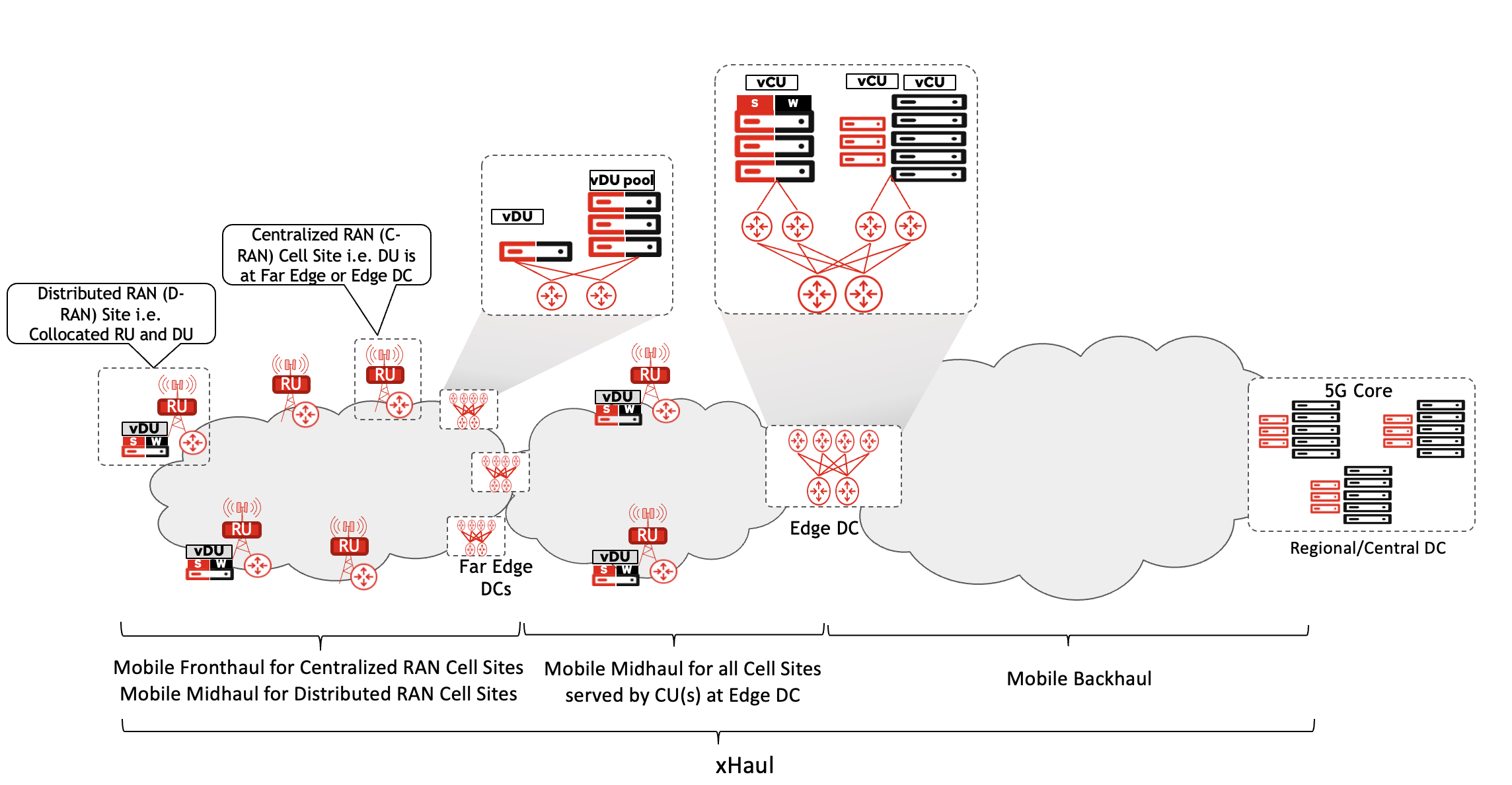
The resulting architecture now looks like the following:
- The cell sites could comprise just the Antenna and RU. DU and CU (collectively forming the BBU) can be on the same site, but don't have to be. The RU, DU and CU collectively make up the 5G’s version of NodeB, called gNB.
- The DUs for multiple sites can be pooled at a location within a dozen or so kilometers away from these cell sites. The small data center hosting these DUs is referred to as "FarEdge Data Center". These DUs could still be physical devices, but with virtualization and containerization technologies catching up, most vendors and operators have leaned towards use of containerized DU running on bare metal servers, commonly referred to as vDU.
- The CUs can be hosted at the Far Edge DC, but when logically possible it is more feasible to pool them at a location that may be farther away from the cell site compared to the DU sites. Thus, the CUs serving multiple cell sites in a given radius could be at the "Edge Data Center". The Edge DC truly materialized the concept of a BBU Hotel. These CUs too could be virtualized - or rather containerized - applications running on commercial off the shelf servers. Given the not-so-strict latency requirements, the virtual implementation of CU, called vCU, could also be hosted on a public cloud environment instead of a DC owned by mobile service operator - but more on this in a different blog.
The network between the FarEdge and Edge DC (to connect the CU and DU) previously didn't exist when the BBU was a single entity. To distinguish this network from Fronthaul and Backhaul, the term Midhaul was used. Collectively the FrontHaul, MidHaul and BackHaul networks are referred to as xHaul. A great amount of consideration and planning is needed for properly designing these networks, and will be discussed separately. A disaggregated and decomposed RAN architecture comprising the RU, DU, and CU in geographically diverse locations is shown in the following figure.
These architectural changes resulted in the myriad of RAN terminologies that are used today.
- From a deployment and placement perspective, when the DU and RU are collocated at the cell site, it is referred to as Distributed RAN (D-RAN). In contrast, if the DU is moved away to a FarEdge or Edge DC, then the RAN implementation is called Centralized RAN or C-RAN.
- The implementation of RAN functions, specifically the CU and DU, as virtual functions (either as VM or Containers) running on general-purpose hardware is referred to as virtualized RAN or vRAN.
- When the CU and DU are implemented as cloud native functions (typically as containers), the deployment is referred to as Cloud-RAN.
- Last, but not least, is the use of the term O-RAN. This refers to the use of open interfaces between the RAN components (that is, the RU, DU, and CU), as specified by the O-RAN alliance.
These terms are not mutually exclusive, as may already be evident. A RAN can be O-RAN compliant (using open interfaces), Cloud-RAN (using cloud native DU/CU), and D-RAN (DU and RU collocated at the cell site) at the same time. Similarly, an O-RAN compliant implementation can be done using special purpose hardware - i.e. not vRAN. However, generally speaking, O-RAN compliant Cloud/Virtual RAN is the path the industry is heading towards. In short, the RAN has evolved significantly over the past several decades across multiple mobile generations leading up to the disaggregated, decomposed Cloud RAN that is quickly becoming the industry norm.
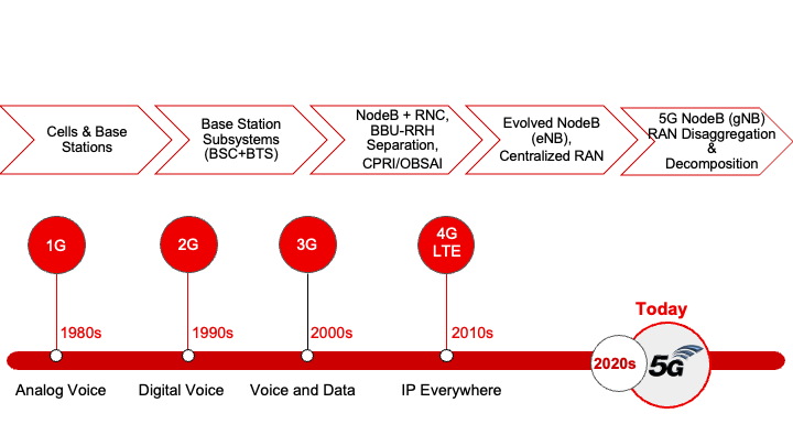
The figure below summarizes fundamental changes and enhancement in RAN across the mobile generations: